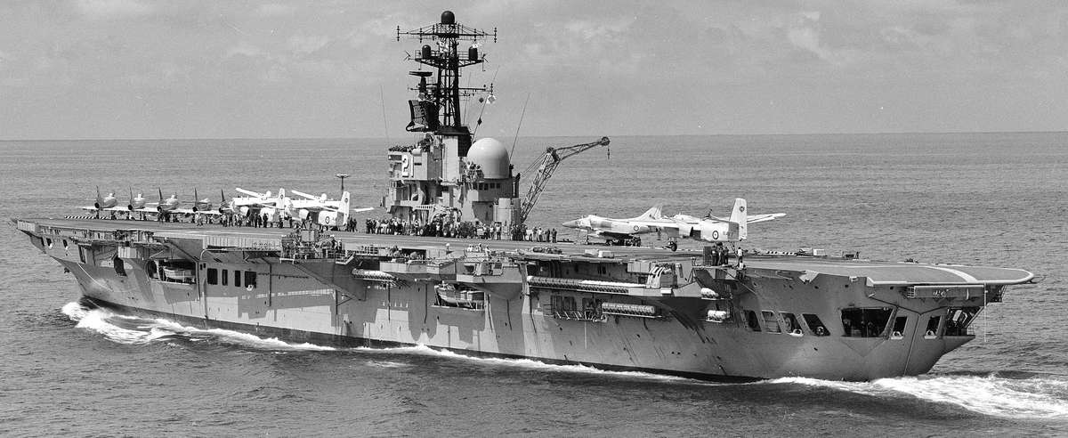
HMAS Melbourne. The Mirror Landing Aid can be seen midships, port side (abeam the radar dome). A Grumman S2 Tracker is about to touch down, which gives a good appreciation of how small the deck was.
By Wilf Hardy.
Note by author. I am not an aviator. So I expect pilots who operated from MELBOURNE may believe that at times I am stating the bleeding obvious in this article. Description of some basic carrier landing procedures are included solely for those readers unfamiliar with these operations. From the late 60s through the 80s I had almost unique knowledge of radar systems and air navigation aids within the FAA and worked closely with navy air traffic controllers. I have therefore decided to record this tale before it is lost forever as I doubt there is anyone else still about who knows the full story of the difficulties encountered with the installation and calibrating of MELBOURNE’s approach and landing aids. Readers may doubt that I could remember such detail after all these years, but at 79 years of age, I am aware that I am now afflicted with that disease of the elderly where one can remember great detail from 50-60 years ago, but haven’t got a clue what took place yesterday!
With the acquisition of A4 Skyhawk and S2 Tracker aircraft in the late 60s, a Carrier Control Approach (CCA) radar system was purchased to integrate an aircraft landing approach with the MELBOURNE’s Mirror Landing Aid (mirror). The CCA was similar in function to the Ground Control Approach (GCA) radar system which I had set to work at NAS Nowra 1967-68, but of much later design and stabilised for 3 degrees of roll and 1.5 degrees of pitch.
The procedure was for an aircraft to do a straight-in approach from 5 miles directly astern of the carrier’s offset runway, conned by radio onto glideslope and centreline cursors of a radar display, by air traffic controllers. When the aircraft reached the transition point 0.5 miles from the ship, the pilot would be advised to “look up and land” when he would take his eyes off the instruments and look for the reflected orange blob (“meat ball”) in the mirror. Provided the aircraft was correctly placed on the radar display cursors, only small corrections would be required to hold the image centred and make a successful landing. However, there were many problem to solve before the integration of these two systems could be confidently trialled.
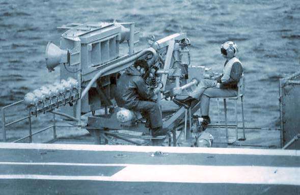
Below: HMAS Melbourne’s Mirror Landing Aid. LH Photo LEUT Weaver. Both images via Phil Thompson

The CCA was absolutely vital for the safe landing of the A4 in IFR conditions. The A4 was a single crewmember aircraft and as a veteran pilot once told me, at night, approaching the ship at high speed, close to the sea, to look up from the instruments and not see the mirror was absolutely terrifying. The Tracker was better placed in that two pairs of eyes were in the cockpit and the Tacho would call “ball” on acquiring the mirror to alert the pilot to look up from the instruments.
I had been trained as a radar tech by the junior service and after discharge following three years maintaining an air defence radar system in Malaya during the Malayan Emergency, took a job at Garden Island Naval Dockyard. Many naval personnel had bitter experiences with G.I. workmen, however it should be realised there were two distinctly different groups employed in the dockyard. There were the blue collar workers, casual employees many of whom were militant unionists. Then there was the smaller dockyard staff group consisting of professional and sub-professional permanent public servants employed by the Department of Defence (Navy). This latter group would be seen working on weapons and electrical systems usually in collar and tie and white overalls; many were ex-servicemen. The group’s function included sea tuning and sea trials of ships following refits and most had wardroom status. I was a Technical Officer in this group.
After successfully setting to work the GCA at NAS Nowra it was inevitable that I would be tasked with similar work for MELBOURNE’s CCA. However the first thing I noticed was that the installation manual was virtually useless to me as the system had never been envisaged to be installed in such a small ship! It was thus necessary to brush up on my trigonometry, have the flight deck surveyed and to find the exact location of the radar antennae with respect to the deck and get on with it. Then other problems surfaced.
Excerpt from USN Manual ADA087012 on the Field of View Requirements for a Carrier Landing give a good explanation of how the Mirror Landing System is used by pilots.(via Phil Thompson. Click to enlarge.)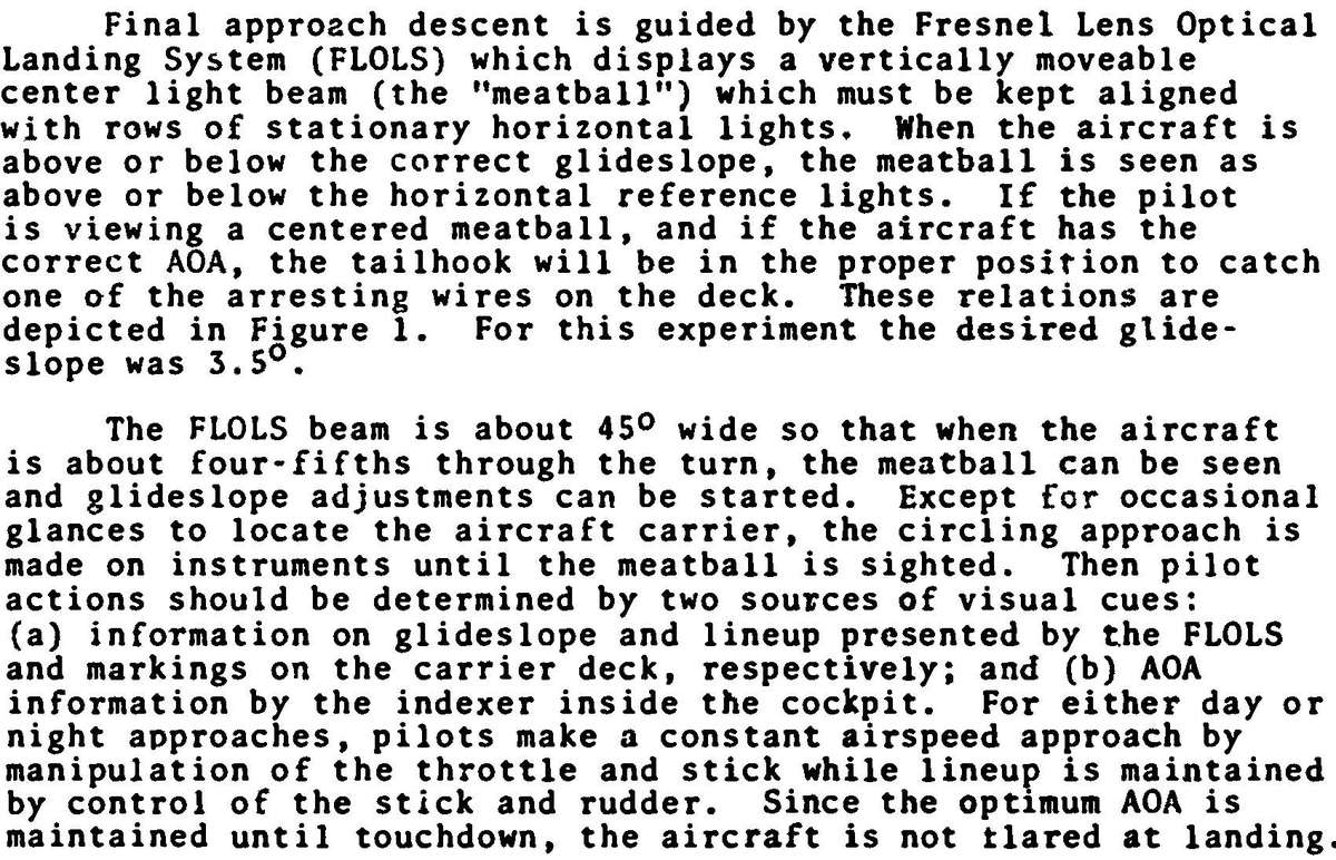

Before I could do anything, the mirror location and landing glideslope had to be determined. The limitations of the ship have often been stated but I have never seen any mention of the intense difficulty in setting up the mirror landing aid. The offset runway was around 600 feet from round-down to the deep drop into the sea at the forward end. The sixth arrestor wire was removed as it was too far down the runway to be of any use to the new fixed wing aircraft. I would look at the short distance between the first and fifth arrestor wires and marvel at how tight the landing area was. I recall being told that the first A4 landing carried out (by a USN A4), resulted in the pilot saying something like “Thank ….. I never have to do that again!”
The G.I. naval architect met with the joint service/civilian team on the flight deck and pointed out the problems. The A4 approached with a very high angle of attack at 120 knots. The most important parameter to consider was the vertical distance from the pilot’s eye (which would be looking at the “meat Ball” in the mirror) and the aircraft’s arrestor hook, which had to clear the round-down. The A4 had a hook to eye distance of some 16 feet and to ensure some clearance at the round-down, the mirror would have to be raised. The problem then was the Tracker with its far greater wingspan would risk striking the mirror with the left wingtip, particularly if the left main gear tyre burst. The hook to eye distance of the Tracker was similar to the A4.
One method to alleviate this problem was to lower the mirror by increasing the glideslope angle, however I was shocked to hear the naval architect state that if the glideslope reached 4.0 degrees, the wheels of the A4 would smash right through the steel deck plate. (I recall being on the flight-deck after the ship was de-commissioned and been staggered by the deep dents in the deck where A4 main wheels had struck the deck whilst landing very short and close to the round down). Fortunately, with the ship steaming at 22 knots and the A4 approaching at 120 knots, the glideslope was effectively reduced by 0.5 degrees. After considerable discussion a 3.5 degree glideslope was agreed as the best compromise and even then, with a level deck and the hook taking the third wire, there was only three feet hook clearance over the round-down – and just about everything was to be a compromise with very little room for error!
The next task was to ensure the CCA radar aircraft echo on the display cursors would provide the best possible transition at ½ mile for the pilot from instruments, to visually acquire the mirror. The problem here was that the centre of the radar echo on the A4 was some 6 feet below the pilot’s eye, but on the Tracker it was close to the pilot’s eye mainly due to the engine locations and propellers. Another compromise. A radar corner reflector was provided with the equipment to be temporarily mounted at the round-down at a height of the centre of the A4 radar echo, thus aiding calibration. I recall looking at this and marvelling at how perilously close it looked to the deck!
Having calibrated the radar to the agreed measurements the system had to be trialled. Now the MELBOURNE was usually berthed stern first toward Wooloomooloo, but there was no way any type of aircraft could be flown down a 3.5 degree glideslope over the Sydney CBD and clear the city buildings. We arranged to turn the ship around so that a Wessex helo could be flown down the glideslope passing low over the northern harbour shoreline in the region of the suburb of Mossman. A surveyor’s theodolite was located on the centreline of the offset runway with the eyepiece aft of the third arrestor wire on the extension of the glideslope. A radio was provided to hear the controller call “on” when the aircraft was on glideslope and centreline and any error was easily noted on the instrument’s graticule, which was conveniently calibrated in tenths of a degree. The instrument presented an inverted image which makes a Wessex look a little strange with its wheels at the top and rotor blades at the bottom! I had done this at Nowra, so as I had the experience, I made the measurements. It may seem somewhat suspect that I was trialling my own work, however every one of us in the small service/civilian team was very much aware of the deadly consequences of getting it all wrong and we worked to ensure whoever in the team had the relevant expertise did the job in hand. The calibration proved well within the system tolerance of 0.2 degree which equated to the aircraft being within about two feet of glideslope and centreline at half a mile.
We had completed the third or fourth run when an urgent telephone call was taken on the ship from Taronga Park Zoo begging us to cease the low helo flights over the elephant compound as the animals were on the verge of stampede!
So to sea trails, when it was found that although holding an aircraft on glideslope was very satisfactory, it could not be held on centreline. I recall meeting with the controllers and coxswain in the ship’s wheelhouse when we were surprised to hear that it was virtually impossible to hold the vessel on a given bearing better than 2.0 degrees; some ten times worse than the accuracy of the radar! However the controllers soon developed a procedure whereby they brought the aircraft in more or less parallel and left of the centreline cursor, slowly closing and were able to get the aircraft close to the required position at transition. Having worked with Navy’s air traffic controllers over a number of years I can say categorically, they were equal or better than any I had worked with previously and it was a sad day when the branch was quite unnecessarily disbanded some years later.
So we got it right. I never heard throughout the remaining life of MELBOURNE of any dangerous situation in the landing phase of any aircraft due to incorrect calibration of the CCA. Although once I was consulted on my opinion as to whether the CCA could have been responsible for an A4 landing short with its main wheels striking the round-down. After discussion it was agreed that this was highly unlikely.
I transferred to NAS Nowra in 1972, culminating in the position of Facilities Development Officer and managing many navigation aid, infrastructure and building projects costing many millions of dollars in the first major redevelopment of the air station in the 80s and early 90s. Of the many projects I was associated with in my 30 years working for Navy (21 years at Nowra), I will always remember the CCA on MELBOURNE as the most demanding, worrying and yet satisfyingly successful projects I was ever associated with.
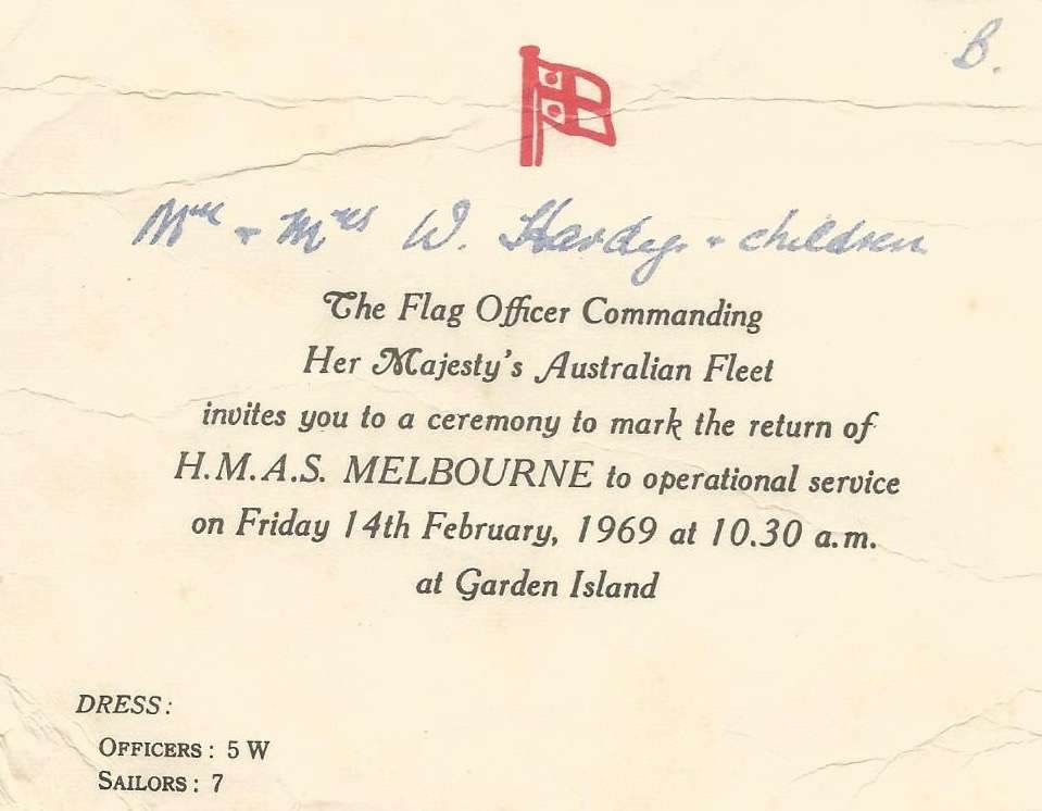 Mr Hardy’s invitation to attend a ceremony on HMAS Melbourne in recognition for his work.
Below. HMAS Melbourne, complete with CGA radar, being towed to the breaker’s yard (image via Phil Thompson)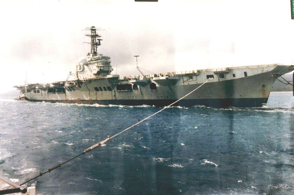
As a footnote, in 1985 I recall seeing video on TV of the old MELBOURNE clearing Sydney heads under tow on its way to the breakers yard in China. I was puzzled to see the fibreglass CCA radome still on the ship, as to remove the CCA radar the radome had to be lifted off first. So why put the radome back on after removing the equipment? The answer to this question was provided a few weeks later when I took an urgent telephone call from Navy Office asking if we had the radar equipment at NAS Nowra. Oops! No wonder the Chinese were surprised at the amount of equipment which had been left in the ship.
Wilf Hardy
Former Senior Technical Officer
Department of Defence (Navy)